Development milestones
First flight: May 24, 1956
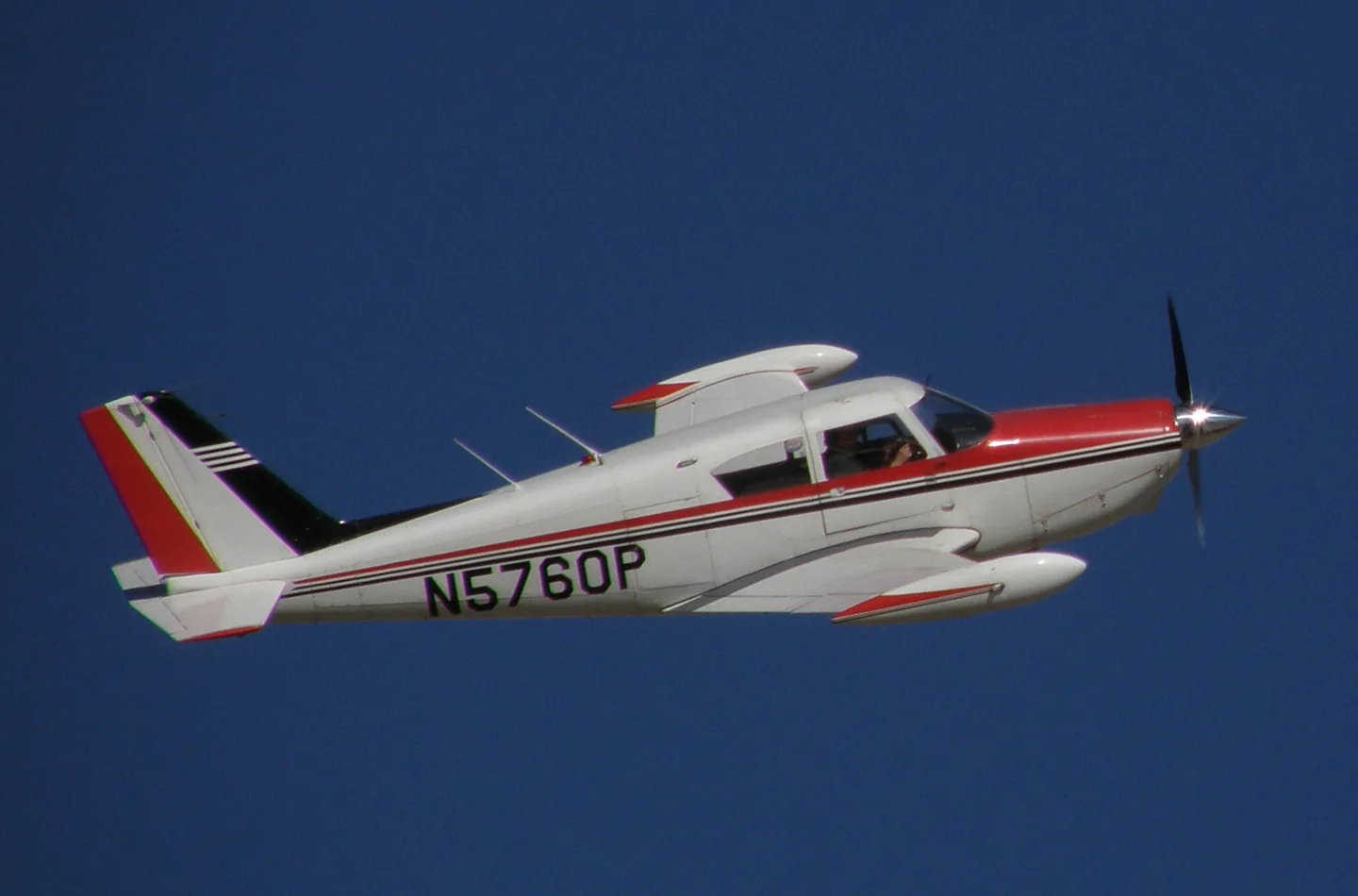 Alan Radecki Akradecki · CC BY-SA 4.0 · Piper PA-24 Comanche pictured
Piper's Comanche first flew in 1956 with an all-metal low-wing airframe, enclosed cabin and retractable tricycle gear. Later versions changed engine power and seating, alongside the separate Twin Comanche line.
Production ended after the 1972 flood at Piper's Lock Haven plant. A2A models a particular Comanche with persistent engine and airframe condition; its manual describes the loading, maintenance and mechanical systems included in the simulation.
Piper PA-24 Comanche · Specifications (PA-24-260C) · real aircraft; source units retained
More about this aircraft on AirframeDB
First flight: May 24, 1956
The Comanche 250’s pitch control uses a stabilator: the horizontal tail moves as a unit instead of carrying a separate hinged elevator. Its anti-servo tab also provides longitudinal trim. A2A’s aircraft description pairs that arrangement with manually operated flaps and conventional yoke-and-pedal controls. This combination gives the cockpit several distinct mechanical controls, even before the separate engine and propeller levers are considered.
An electric motor and reduction mechanism beneath the floor move the three landing-gear units through push-pull cables. The nosewheel steering disconnects as the gear retracts, reducing the steering mechanism’s contribution to airborne rudder-pedal loads. The manual also describes a ground anti-retraction switch and separate indications for gear position. The selector operates the documented electrical and mechanical landing-gear system.
The list supplies trim-required lights and AP controls, and identifies the elevator trim handle with a standard SimVar requested in percent.
Unwin flew Mark Bonsall's refurbished 1963 Comanche 250 from Netherthorpe with instructor Nick Riddin. This particular aircraft had fuel injection and a three-blade propeller, so it was not an untouched factory example. With two aboard and partial fuel, it accelerated briskly from the grass strip. Unwin liked the harmonisation of the primary controls and their low initial resistance, although he found the older instrument and engine-control layout less intuitive than a modern cockpit. In airwork, his stalls gave clear warning and little inclination to drop a wing.
The landing and photo flights exposed different demands. He could feel the aircraft entering ground effect and thought excess approach speed would produce a long float; careful speed control rewarded him with successive satisfactory landings. Flying close formation for the photographer required more work, partly because the view from his chosen seat was restrictive. His overall appreciation was for a capable touring aircraft, with handling observations tied to the loading and modifications of the example he actually flew.
Wall's attachment to the Comanche began with a flying-club comparison in 1958. Interviewed by Bill Cox, he recalled flying a loaded Comanche 250 and a contemporary Bonanza between Burbank and Phoenix. He considered the Comanche the stronger performer in that particular comparison, while acknowledging the appeal of the Beechcraft's handling. Decades later, after a professional flying career, that experience helped draw him back to a 1958 Comanche of his own.
By the 2005 article, Wall had accumulated more than a thousand hours in the type and restored his aircraft extensively. He distinguished brochure claims from his experience: the advertised climb figure seemed optimistic to him, while maximum cruise was closer to what he observed. His usual choice was an economical high-altitude cruise rather than maximum speed. As an owner and mechanic, he also valued access for maintenance and familiarity with the systems he had rebuilt. These are the preferences and reported results of one experienced owner, rather than a controlled comparison of all Comanches and Bonanzas.
Looking back on his test-flying years, Kershner remembered the Comanche 400 as one of the aircraft that stood out. He identified the two final test aircraft and explained Pug Piper's interest in obtaining high-altitude performance without turbocharging. The extra power gave him an impression reminiscent of a fighter, but he also recalled substantial fuel consumption and troublesome hot starts during the flight-test period. His account concerns the eight-cylinder 400, a different proposition from the familiar 180 and 250.
One flight supplied the story's human detail. Over Lock Haven, he overtook a conventional Comanche and made further passes that prompted its pilot to ask what version he was flying. Kershner gave an evasive answer over the radio, then returned to a reprimand for drawing attention to an aircraft Piper had not yet announced. He also remembered watching the fuel indication move towards empty.
In the manual's developer notes, Gentile explains why A2A chose his own Comanche 250, N6229P, for its new Accu-Sim system. He had owned and operated the aeroplane for more than a decade. That familiarity gave the team continuing access to an aircraft they could examine and fly while investigating questions raised during development. His account describes the connection between an owner's long experience and the choice of a simulation subject.
Gentile's affection is equally explicit. He values the Comanche's combination of speed, load-carrying ability, cabin room and manageable handling, and says the aircraft has become part of the family. The appeal began with its appearance and deepened over years of operation. This is an enthusiastic owner's introduction, written by the developer selling the simulation, rather than an independent comparison flight.
Piper's Comanche first flew in 1956 with an all-metal low-wing airframe, enclosed cabin and retractable tricycle gear. Later versions changed engine power and seating, alongside the separate Twin Comanche line.
This profile selects A2A Comanche 250 for MSFS 2020, MSFS 2024.
The stabilator/anti-servo arrangement motivates reversible yoke loading. Spring resistance builds with the selected airspeed response. A separate aerodynamic term adds speed-dependent control load.
The anti-servo tab supplies pitch relief; ALT-mode trim lamps request manual action. Valid trim provides the configured pressure relief. Autopilot following is enabled for supported control references.
The Comanche’s manually controlled stabilator uses an anti-servo tab for longitudinal trim. A2A’s S-TEC30 altitude hold has an elevator servo and lamps requesting pilot trim, without automatic pitch trim. Native 2024 GPSS supplies lateral steering as a separate addition.
A2A’s native 2024 Comanche removes the earlier Elevator Force tablet input option and adds ST901 GPSS lateral guidance; S-TEC30 ALT still requests manual trimming.
The gains are normalized profile settings. They describe the chosen effect balance; hand force depends on the device and its output limits. IAS references are tuning values rather than operating limits. Physical acceptance of this revision remains pending.
The final overall output scale applied to everything the model produces, before the device cap.
More: everything (spring, loads, effects) gets stronger together.
Less: everything softens together.
Why here: Scales overall profile strength while preserving effect balance, subject to device and output limits.
The base centring force that pulls the stick back to centre. Every other force stacks on it. Too low and the stick feels limp in normal flight; too high and it fights your hand and masks the smaller cues layered above it.
More: firmer centring that resists your hand at all times.
Less: a limper stick that leans on aerodynamic load alone.
Why here: The stabilator/anti-servo arrangement motivates reversible yoke loading. The baseline spring is 0.74. Its low-speed blend reaches baseline strength at 75 KIAS.
Comanche Pilot ManualComanche variables listExact product and documentation researchNative ComancheA small neutral zone around centre where the spring stays quiet, so tiny movements at rest don't chatter. Wider is calmer but looser; narrower is more precise but can twitch around centre.
More: a calmer but looser centre with more free play.
Less: a tighter centre that may chatter at rest.
Why here: Sets travel around the centre before the baseline spring resists. Smaller values engage it sooner.
A master scale over both sustained axis loads, applied before their independent balance. Profiles normally leave this alone and tune the two axis loads instead.
More: both axes load up harder.
Less: both axes lighten together.
Why here: The aerodynamic-load gain is 0.8 with an indicated-speed reference of 150 KIAS. This supplies speed-dependent loading alongside the spring.
Enables the low-speed spring engagement window (start/full knots above). Off, the spring is constant at all speeds.
Why here: Allows baseline spring strength to rise with indicated airspeed where the control law permits it.
How much of the spring survives at a standstill, before airspeed can build any aerodynamic force. A high floor keeps the parked stick firm; a low floor gives the loose, cable-slack feel of a parked light aircraft.
More: a firmer stick while parked and taxiing.
Less: a floppier parked stick that only wakes up with airspeed.
Why here: Sets low-speed spring strength as a fraction of baseline when blending is enabled. One keeps full strength.
The airspeed where the spring begins climbing from its low-speed floor toward full strength: the controls "coming alive" on the takeoff roll.
Why here: Sets the IAS where the low-speed spring blend starts rising. This is a feel threshold, not a flight limit.
The airspeed where the spring reaches full strength. Between the start and this point, centring firms up progressively as airflow builds over the controls.
Why here: Sets the IAS where the low-speed blend reaches baseline strength; high-speed stiffening also uses it.
The indicated airspeed where aerodynamic load reaches its designed full level. It anchors the whole load curve to the aircraft's real speed range: a 172 loads up by 110 knots, a jet much later.
More: loads arrive later; the stick stays light up to a higher speed.
Less: loads arrive earlier and cruise feels heavier.
Why here: Sets the IAS reference for aerodynamic loading. It is an estimate, not published cruise TAS or a flight limit.
How much the centring itself stiffens with speed, on top of the deflection loads. Zero keeps centre feel constant; more makes the stick centre harder at cruise and looser in the pattern.
More: a centre that hardens noticeably as you go faster.
Less: constant centre feel at every speed.
Why here: The high-speed spring-stiffening gain is 0.15. It strengthens the permitted spring response above 75 KIAS, with the squared-speed ratio capped at 5.
The upper limit on speed-driven centre stiffening, so very fast flight can't wind the spring up without bound.
More: more total stiffening allowed at high speed.
Less: stiffening clamps off sooner.
Why here: Limits the squared airspeed ratio used for high-speed spring stiffening; it is not a device-force cap.
The sustained roll load from aileron deflection and airspeed, balanced independently of pitch. Together with the elevator load it sets the control-harmony ratio reviewers talk about.
More: heavier roll forces.
Less: lighter, quicker-feeling ailerons.
Why here: Roll and pitch aerodynamic scales are 0.72 and 1, respectively. They set the aerodynamic axis balance. No custom spring-travel curve is enabled.
The sustained pitch load from elevator deflection and airspeed, balanced independently of roll. This is the main lever behind a type's pitch weight. It does not touch aileron, spring, trim, or buffet forces.
More: heavier sustained pitch forces at speed.
Less: a lighter elevator that takes less muscle to hold.
Why here: Scales pitch aerodynamic loading; pitch spring travel and trim responses are separate settings.
A cap on each steady pitch or roll force before it reaches the device, guarding against slamming or saturating the hardware in strong maneuvers.
More: stronger peak steady forces before clipping.
Less: a gentler ceiling; hard maneuvers flatten out sooner.
Why here: Caps directed-force output. Native spring effects and device limits remain separate.
How strongly elevator trim relieves held pitch force and shifts where the stick settles. At 100%, a properly trimmed aircraft needs no held pressure, the trim-away-the-load workflow of real flying.
More: trim removes more of the held pitch force; at 100% full trim zeroes it.
Less: you keep holding force even when trimmed.
Why here: The anti-servo tab supplies pitch relief; ALT-mode trim lamps request manual action. Pitch authority 0.3 provides load relief and permitted centre movement; roll authority is 0.
Comanche Pilot ManualComanche variables listExact product and documentation researchNative ComancheThe same relief for roll trim. Most GA types have no real aileron trim, so this stays at zero; types with roll trim get a matching value.
More: roll trim removes more held roll force.
Less: roll trim does less.
Why here: Scales supported roll-trim relief and permitted centre movement. Zero removes roll response.
Rolling surface vibration from wheel speed and surface type: pavement, grass, or gravel under the gear.
More: louder surface texture through the stick.
Less: a smoother taxi.
Why here: Sets rolling texture strength, modified by speed, surface and undercarriage configuration.
Short discrete bumps from expansion joints, ruts, and rough surface, punctuating the continuous rumble.
More: sharper hits from joints and ruts.
Less: softer ground detail.
Why here: Sets gear-bump texture during ground motion, separate from touchdown impact.
Airframe shake approaching the stall and while the stall warning is active: how loudly this wing announces it is unhappy. Types with a crisp break get modest buffet and let the horn carry the warning.
More: a louder pre-stall shake.
Less: a quieter wing; the horn carries the warning.
Why here: Sets stall-buffet strength. Zero removes the cue without changing simulator stalls or warnings.
Transonic buffet approaching the Mach limit. Meaningful for jets near MMO, zero for pistons and turboprops that never get there.
More: stronger transonic buffet near the Mach limit.
Less: a smoother high-Mach ride.
Why here: Sets high-Mach buffet strength; onset and full-strength thresholds are separate.
Low-frequency airframe vibration with flaps extended into the airflow, in the speed window where they actually work the air.
More: a rougher ride with flaps working the air.
Less: smoother approach flap.
Why here: Sets flap buffet at the configured position and speed gates. Flap movement texture is separate.
Airframe drumming from retractable gear hanging in the airstream. Zero for fixed-gear types, where the airframe never changes shape.
More: more drumming with the wheels hanging out.
Less: cleaner gear-down flight.
Why here: Sets gear aerodynamic buffet; movement and ground-contact cues are separate.
The dedicated stall stick-shaker buzz, fired by the aircraft's own stall-warning system. Only types with a real shaker get a value; everything else relies on aerodynamic buffet and the horn.
More: a harder stick-shaker buzz.
Less: a subtler shaker.
Why here: Sets triggered shaker strength; inactive while the shaker feature is disabled.
The one-shot kick when the wheels meet the runway, scaled by sink rate: a greaser whispers, a firm arrival thumps.
More: a harder kick at touchdown.
Less: softer arrivals.
Why here: Sets landing-impact strength; landing telemetry and response shape determine the pulse.
Rollout vibration while reverse thrust or beta-range props are working. Zero for types without reverse.
More: a rougher rollout under reverse.
Less: quieter reverse.
Why here: Sets reverse-thrust vibration with valid reverser and engine conditions. Zero removes the cue.
Continuous powerplant vibration following RPM between idle and full power, the ever-present reminder that something is burning fuel up front.
More: more engine through the stick.
Less: a quieter powerplant.
Why here: Sets estimated engine vibration using configured telemetry and response, not measured cockpit vibration.
Continuous vibration only while the sim reports the flap surfaces actually travelling. It follows real actuator motion and failures, not an estimated timer.
More: more vibration while the flap surfaces travel.
Less: quieter flap runs.
Why here: Sets texture from observed flap movement; a command without movement does not establish the cue.
How far autopilot commands may physically move the stick. Kept tiny in MSFS, where a moved axis can read back as pilot input; zero disables following entirely.
More: the autopilot visibly moves your stick further.
Less: a barely perceptible follow.
Why here: Sets admitted AP-follow gain, not a percentage of travel. Runtime ownership and input limits still apply.
Whether this feature is active in this profile.
Why here: Retained for compatibility and group membership. Trim relief, rather than this flag, controls centre movement.
Whether this feature is active in this profile.
Why here: Allows trim relief with supported control law and valid telemetry. Axis authorities set its amount.
Whether this feature is active in this profile.
Why here: Enables local force trim, separate from aircraft-owned trim and add-on integration qualification.
Whether this feature is active in this profile.
Why here: Allows load-factor changes to modify permitted spring laws. Passive fly-by-wire feel can suppress it.
Whether this feature is active in this profile.
Why here: Enables rate damping with the configured coefficients and control law.
Whether this feature is active in this profile.
Why here: Following is on at 1 authority when a supported, valid autopilot control reference is available.
Whether this feature is active in this profile.
Why here: Permits centering hold during a supported AP state, separate from following a moving target.
Why here: Sets admitted AP neutral-hold strength; inactive while neutral hold is disabled.
Whether this feature is active in this profile.
Why here: Enables aerodynamic cues; each still needs nonzero strength and its simulator conditions.
Where this effect reaches full strength (or has fully faded, for washouts).
More: a more gradual build to a later peak.
Less: a quicker build.
Why here: Sets the final flap index for detent normalization. UP plus three detents uses maximum index3.
Where this effect begins fading in.
More: the effect begins later.
Less: it begins earlier.
Why here: Sets the first flap detent that admits buffet; this is a handle index, not degrees.
Whether this feature is active in this profile.
Why here: Permits shaker at supported warning conditions; the switch does not establish aircraft equipment.
Whether this feature is active in this profile.
Why here: Enables ground effects; each still needs its own strength and contact or motion telemetry.
Whether this feature is active in this profile.
Why here: Enables engine cues with nonzero settings and valid running-engine telemetry.
Whether this feature is active in this profile.
Why here: Enables accessory cues with configured strengths and observed accessory movement.
The strength of this effect.
More: a stronger effect.
Less: a weaker one.
Why here: Sets texture from observed gear movement, separate from aerodynamic and touchdown effects.
| Parameter | Value | What it controls and why |
|---|---|---|
| Spring strength | 0.74 | The stabilator/anti-servo arrangement motivates reversible yoke loading. The baseline spring is 0.74. Its low-speed blend reaches baseline strength at 75 KIAS. |
| Spring deadband | 0.045 | Sets travel around the centre before the baseline spring resists. Smaller values engage it sooner. |
| Force gain | 0.8 | The aerodynamic-load gain is 0.8 with an indicated-speed reference of 150 KIAS. This supplies speed-dependent loading alongside the spring. |
| Master gain | 0.85 | Scales overall profile strength while preserving effect balance, subject to device and output limits. |
| Dynamic-pressure blend | True | Allows baseline spring strength to rise with indicated airspeed where the control law permits it. |
| Minimum spring factor | 0.5 | Sets low-speed spring strength as a fraction of baseline when blending is enabled. One keeps full strength. |
| Spring wake-up speed | 20 kt | Sets the IAS where the low-speed spring blend starts rising. This is a feel threshold, not a flight limit. |
| Spring full-strength speed | 75.0 kt | Sets the IAS where the low-speed blend reaches baseline strength; high-speed stiffening also uses it. |
| Force tuning speed | 150.0 kt | Sets the IAS reference for aerodynamic loading. It is an estimate, not published cruise TAS or a flight limit. |
| Airspeed spring stiffening | 0.15 | The high-speed spring-stiffening gain is 0.15. It strengthens the permitted spring response above 75 KIAS, with the squared-speed ratio capped at 5. |
| Airspeed stiffening cap | 5 | Limits the squared airspeed ratio used for high-speed spring stiffening; it is not a device-force cap. |
| Aileron force scale | 0.72 | Roll and pitch aerodynamic scales are 0.72 and 1, respectively. They set the aerodynamic axis balance. No custom spring-travel curve is enabled. |
| Elevator force scale | 1.0 | Scales pitch aerodynamic loading; pitch spring travel and trim responses are separate settings. |
| Maximum output force | 0.55 | Caps directed-force output. Native spring effects and device limits remain separate. |
| StickFeel · Trim feel enabled | True | Retained for compatibility and group membership. Trim relief, rather than this flag, controls centre movement. |
| StickFeel · Trim relief enabled | True | Allows trim relief with supported control law and valid telemetry. Axis authorities set its amount. |
| StickFeel · Elevator authority | 0.3 | The anti-servo tab supplies pitch relief; ALT-mode trim lamps request manual action. Pitch authority 0.3 provides load relief and permitted centre movement; roll authority is 0. |
| StickFeel · Aileron authority | 0 | Scales supported roll-trim relief and permitted centre movement. Zero removes roll response. |
| StickFeel · Force trim enabled | False | Enables local force trim, separate from aircraft-owned trim and add-on integration qualification. |
| StickFeel · G load enabled | True | Allows load-factor changes to modify permitted spring laws. Passive fly-by-wire feel can suppress it. |
| StickFeel · Rate damping enabled | True | Enables rate damping with the configured coefficients and control law. |
| Autopilot · Follow enabled | True | Following is on at 1 authority when a supported, valid autopilot control reference is available. |
| Autopilot · Follow authority | 1.0 | Sets admitted AP-follow gain, not a percentage of travel. Runtime ownership and input limits still apply. |
| Autopilot · Neutral hold enabled | False | Permits centering hold during a supported AP state, separate from following a moving target. |
| Autopilot · Neutral hold strength | 0.6 | Sets admitted AP neutral-hold strength; inactive while neutral hold is disabled. |
| Aero · Enabled | True | Enables aerodynamic cues; each still needs nonzero strength and its simulator conditions. |
| Aero · Gain | 0.35 | Sets stall-buffet strength. Zero removes the cue without changing simulator stalls or warnings. |
| Aero · Gain | 0 | Sets high-Mach buffet strength; onset and full-strength thresholds are separate. |
| Aero · Gain | 0.14 | Sets flap buffet at the configured position and speed gates. Flap movement texture is separate. |
| Aero · Max flap index | 3 | Sets the final flap index for detent normalization. UP plus three detents uses maximum index3. |
| Aero · Min flap index | 2 | Sets the first flap detent that admits buffet; this is a handle index, not degrees. |
| Aero · Gain | 0.1 | Sets gear aerodynamic buffet; movement and ground-contact cues are separate. |
| Aero · Shaker enabled | False | Permits shaker at supported warning conditions; the switch does not establish aircraft equipment. |
| Aero · Amplitude | 0.5 | Sets triggered shaker strength; inactive while the shaker feature is disabled. |
| Ground · Enabled | True | Enables ground effects; each still needs its own strength and contact or motion telemetry. |
| Ground · Gain | 0.4 | Sets rolling texture strength, modified by speed, surface and undercarriage configuration. |
| Ground · Gain | 0.25 | Sets gear-bump texture during ground motion, separate from touchdown impact. |
| Ground · Gain | 0.65 | Sets landing-impact strength; landing telemetry and response shape determine the pulse. |
| Ground · Gain | 0 | Sets reverse-thrust vibration with valid reverser and engine conditions. Zero removes the cue. |
| Engine · Enabled | True | Enables engine cues with nonzero settings and valid running-engine telemetry. |
| Engine · Gain | 0.12 | Sets estimated engine vibration using configured telemetry and response, not measured cockpit vibration. |
| Mechanical · Enabled | True | Enables accessory cues with configured strengths and observed accessory movement. |
| Mechanical · Gain | 0.12 | Sets texture from observed flap movement; a command without movement does not establish the cue. |
| Mechanical · Gain | 0.12 | Sets texture from observed gear movement, separate from aerodynamic and touchdown effects. |
If your time in the type says this page got something wrong, correct it here.
This page is built from cited references, and real time in the type beats a citation. Quote the claim that reads wrong and tell us what the actual aircraft does. Corrections go to the maintainer for review and feed the next revision of this research.
Open conversation about flying and tuning the Piper Comanche, in the community forum. Corrections above go privately to the maintainer; hangar talk is public.